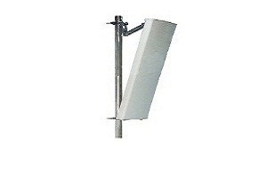


Multi-system common mode antenna
Name:4488 ba
Model:基站板狀天線
Frequency:820-880/1710-2170
Gain:13-15
Negative Way:+45°
Standing Wave Ratio:90
Product Features:

Electrical indicators | ||||
Working frequency (MHz) | 885-960 | 885-960 | 1710-1830 | 1710-1830 |
Polarization mode | ± 45° polarization | |||
Gain (dBi) | ≥13.5 | ≥16 | ||
Horizontal beam width (°) | 65 ± 8 | 65+6, 65-9 | ||
Vertical beam width (°) | 14 | 7 | ||
Electric down angle range (°) | 0-14 | 0-14 | 2-12 | 2-12 |
Upper side lobe suppression (dB) | ≥15 | ≥15 | ||
Front-to-back ratio (dB) | ≥25 | ≥25 | ||
Cross polarization ratio (dB) | Axial ≥15; within ±60° ≥8 | |||
Voltage standing wave ratio | ≤1.5 | |||
Isolation (dB) | ≥25 | |||
Third-order intermodulation (dBm) | ≤-107 | |||
Second-order intermodulation (dBm) | ≤-120 | / | ||
Power capacity (W) | 500 | 300 | ||
Impedance ( Ω ) | 50 | |||
Lightning protection | Directly grounded | |||
Electrical indicators | ||||
Working frequency | 1885-1920&2010-2025 | 2515~2675 | ||
1885-1920 | 2010-2025 | 2515~2675 | ||
Electric down angle range (°) | 2-12 | 2-12 | ||
Electric down angle accuracy (°) | ± 1 | ± 1 | ||
Calibration parameters | ||||
Coupling degree from calibration port to each radiation port (dB) | -26±2 | |||
The maximum deviation of the amplitude from the calibration port to each radiation port (dB) | ≤0.7 | |||
Maximum phase deviation from calibration port to each radiation port (°) | ≤5 | |||
Calibration port and radiation port voltage standing wave ratio | ≤1.5 | |||
900- pair F- band second-order transmission intermodulation (dBm) | -120 | / | / | |
Co-polarized port isolation (dB) | ≥25 | |||
Different polarization port isolation (dB) | ≥25 | |||
Isolation between FA/D systems (dB) | ≥30 | |||
Unit beam | ||||
Horizontal beam width (°) | 100±15 | 90±15 | 65±15 | |
Gain (dBi) | ≥13 | ≥13.5 | ≥15 | |
Vertical beam width (°) | / | / | ≥6 | |
Beam ± 60° edge power drop (dB) | / | / | 12 ± 3 | |
Cross polarization ratio (dB) | Axial | ≥15 | ≥15 | ≥15 |
±60° | ≥8 | ≥8 | ≥8 | |
Front-to-back ratio (dB) | ≥23 | ≥23 | ≥25 | |
Upper side lobe suppression (dB) | / | / | ≥13 | |
Broadcast beam | ||||
Horizontal beam width (°) | / | 65±5 | / | |
Gain (dBi) | ≥15 | ≥14 | ≥14.5 | |
±32.5° Sector power ratio ( ﹪ ) | 72 ± 7 | / | 72 ± 7 | |
±60° sector power accounted for ratio ( ﹪ ) | ≥95 | / | ≥90 | |
Beam ± 60° edge power drop (dB) | 12 ± 3 | 12 ± 3 | 12 ± 3 | |
Vertical beam width (°) | ≥8.0 | ≥7.5 | ≥6.0 | |
Cross polarization ratio (dB) | Axial | ≥18 | ≥18 | / |
±60° | ≥8 | ≥8 | / | |
Front-to-back ratio (dB) | ≥25 | ≥25 | ≥25 | |
Upper side lobe suppression (dB) | ≥14 | ≥14 | ≥13 | |
Business beam | ||||
0° pointing beam gain (dBi) | ≥19 | ≥20 | ≥20.5 | |
0° pointing beam horizontal beam width (°) | ≤29 | ≤26 | ≤25 | |
0° pointing beam horizontal sidelobe level (dB) | ≤-12 | ≤-12 | ≤-12 | |
0° Cross polarization ratio ( axial ) (dB) | ≥18 | ≥18 | ≥18 | |
0° front-to-back ratio (dB) | ≥28 | ≥28 | ≥28 | |
±60° pointing beam gain (dBi) | ≥16.5 | ≥16.5 | ≥16.5 | |
±60° pointing beam horizontal beam width (°) | ≤32 | ≤32 | ≤23 | |
±60° point to horizontal sidelobe level (dB) | ≤-5 | ≤-5 | ≤0 | |
Mechanical index | |
Radome material | UPVC |
Mechanical tilt angle (°) | 0-16 |
Connector type | 900/1800: 7/16Din ( female )×4 TD-FA: 4- core /5- core cluster connector ( male ) × 2 TD-D: 4- core /5- core cluster connector ( male ) × 2 |
Antenna size (mm) | ≤ 1600×400×195 |
Antenna net weight (kg) | ≤ 36.0 |
Packing weight (kg) | ≤ 46.0 |
Ambient temperature (°C) | Working temperature : -40~+60; limit temperature : -55~+75 |
Wind resistance (m/s) | Working wind speed : 36.9; Ultimate wind speed : 55 |